May 2024

EXPERIMENT- 4 Anderson’s Bridge

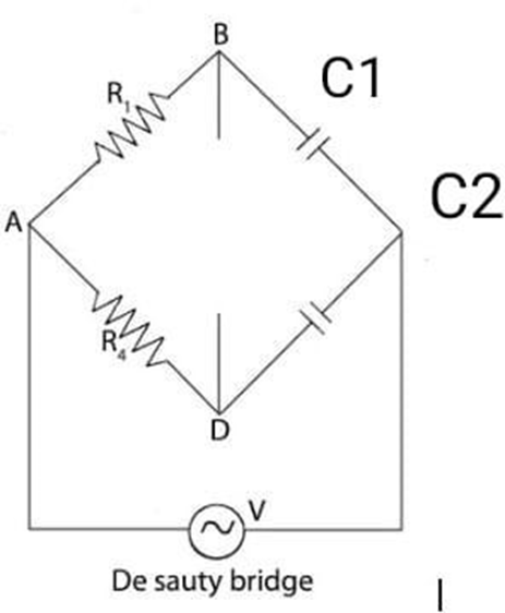
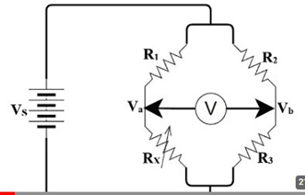
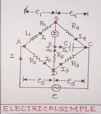
Aim– Measurement of Inductance by Anderson’s Bridge. Material Required– Anderson Bridge Trainer Kit, Wires Theory– The Anderson bridge is a bridge circuit used for measuring unknown resistances, especially those with high values. The bridge is balanced when the ratio of the resistances in the adjacent arms is equal. Circuit Diagram- Formula used and derivation – […]

EXPERIMENT- 4 Anderson’s Bridge Read More »

BASIC INSTRUMENTAION AND MEASUREMENT TECHNIQUES

EXPERIMENT- 2 Wheatstone Bridge.

Aim- Measurement of Resistance by Wheatstone Bridge. Apparatus- Galvanometer (0-10V), Decade Resistance Box, Resistance (4), Bread Board, Power Supply Theory- The Wheatstone bridge works on the principle of null deflection, i.e. the ratio of their resistance is equal, and no current flows through the circuit. When the bridge is balanced, the galvanometer reads zero. This

EXPERIMENT- 2 Wheatstone Bridge. Read More »

BASIC INSTRUMENTAION AND MEASUREMENT TECHNIQUES

Experiment – 6 LVDT

LVDT (Linear Variable Differential Transformer) Aim: To determine the characteristics of LVDT. Apparatus Required: Theory: LVDT is basically a mutual inductance type of transformer with variable coupling between primary and secondary two coupling coils.             LVDT (Linear variable differential transformer) are used to measure displacement. It operates on the principle of a transformer; it consists

Experiment – 6 LVDT Read More »

BASIC INSTRUMENTAION AND MEASUREMENT TECHNIQUES

Experiment 7 Norton’s Theorem

Aim: Verification of Norton’s Theorem Components and Equipment Required:Variable power supply , 3 resistors, resistance box, constant current source, connecting wires Theory:  Norton’s theorem states that a linear two-terminal circuit can be replaced by an equivalent circuit consisting of a current source IN in parallel with a resistor RN, where IN is the short-circuit current

Experiment 7 Norton’s Theorem Read More »

BASIC CIRCUIT THEORY, BASIC CIRCUIT THEORY, SEM 1

Experiment 6 Maximum Power Transfer Theorem

Aim: Verification of Maximum Power Transfer Theorem Components and Equipment Required:Beadboard, multimeter, connecting wires, DC power supply, resistor, resistance box  Theory: According to Maximum Power Transfer Theorem, a linear two terminal network consisting of a voltage source and resistance will transfer maximum power into a load connected between its two terminal when the load resistance

Experiment 6 Maximum Power Transfer Theorem Read More »

BASIC CIRCUIT THEORY, BASIC CIRCUIT THEORY, SEM 1

Experiment 5 Thevenin’s Theorem

Aim: Verification of Thevenin’s Theorem Components and Equipment Required:Multimeter, power supply, breadboard, 3 resistors, connecting wires Theory:Thevenin’s theorem states that a linear two-terminal circuit can be replaced by an equivalent circuit consisting of a voltage source VTh in series with a resistor RTh, where VTh is the open-circuit voltage at the terminals and RTh is

Experiment 5 Thevenin’s Theorem Read More »

BASIC CIRCUIT THEORY, BASIC CIRCUIT THEORY, SEM 1
Scroll to Top