ICs and their Pin Diagrams
https://www.build-electronic-circuits.com/7400-series-integrated-circuits/
ICs and their Pin Diagrams Read More »
DIGITAL ELECTRONICShttps://www.build-electronic-circuits.com/7400-series-integrated-circuits/
ICs and their Pin Diagrams Read More »
DIGITAL ELECTRONICS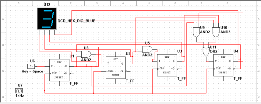
Aim: To design a synchronous non-sequential counter using JK/T flip flop Apparatus: JK flip flop, T flip flop, AND gates, OR gates, Probes, Hex display, connecting wires, Digital interactive signal generators, clock pulse generator. Circuit diagram:
Synchronous non-sequential counter using JK/T flip flop Read More »
DIGITAL ELECTRONICS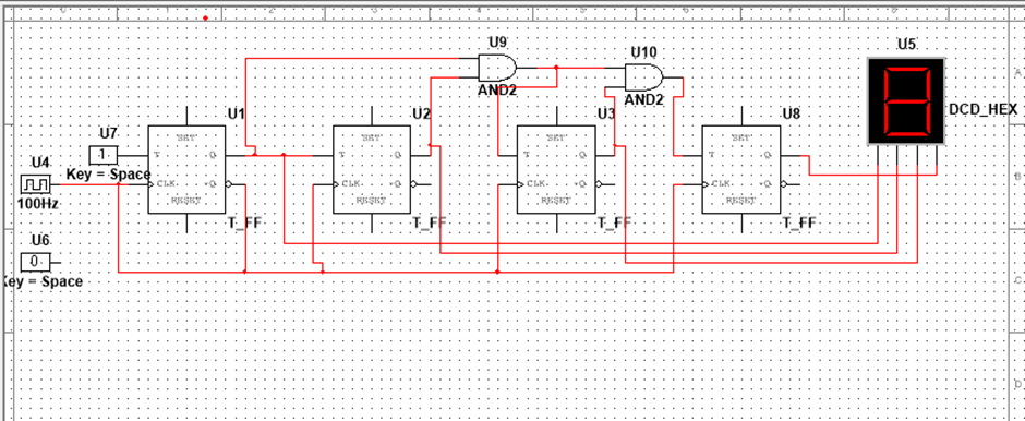
Aim: to design a synchronous/ asynchronous counter using jk/t/d flip flops. Apparatus: jk flip-flop, D flip-flop, T flip-flop, connecting wires, digital signal inputs, display. Circuit Diagrams:
synchronous/ asynchronous counter using jk/t/d flip flops Read More »
DIGITAL ELECTRONICS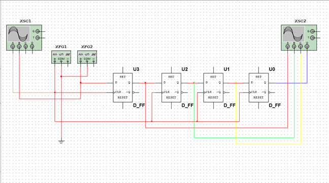
AIM : DESIGN A SISO SHIFT REGISTER. APPARATUS : D_FLIP FLOP (*4), CROs (2), FUNCTION GENERATORs (2), connecting wires. CIRCUIT : OUTPUT :
DESIGN A SISO SHIFT REGISTER. Read More »
DIGITAL ELECTRONICS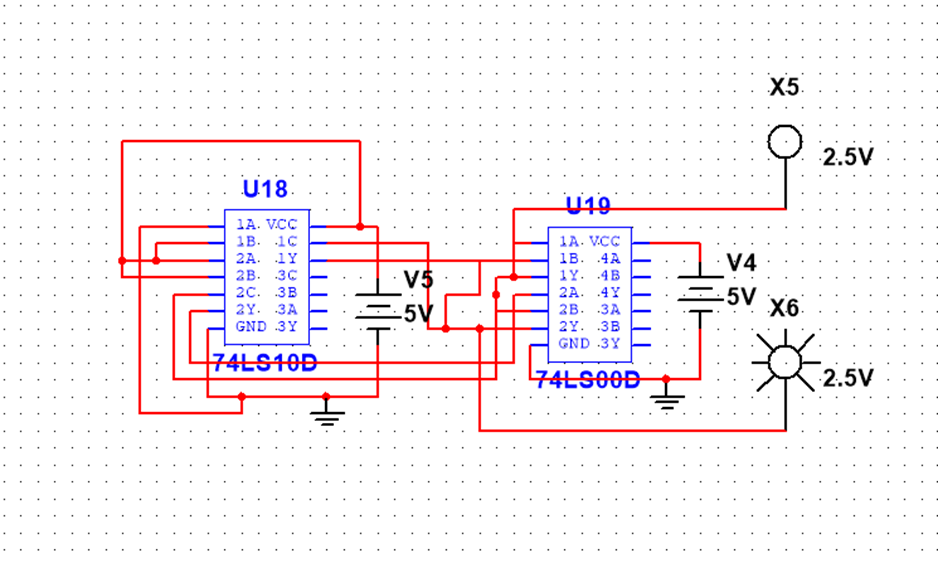
Aim : To build a Flip- Flop Circuits using elementary gates. (RS, Clocked RS, D-type, JK, JK Master slave). Components Required: IC 7400 , IC 7410 , 5v dc power supply , ground Circuit Diagrams and Outputs: D Flip Flop : RS Flip Flop: Clocked RS Flip Flop: JK Flip Flop : Result : Hence
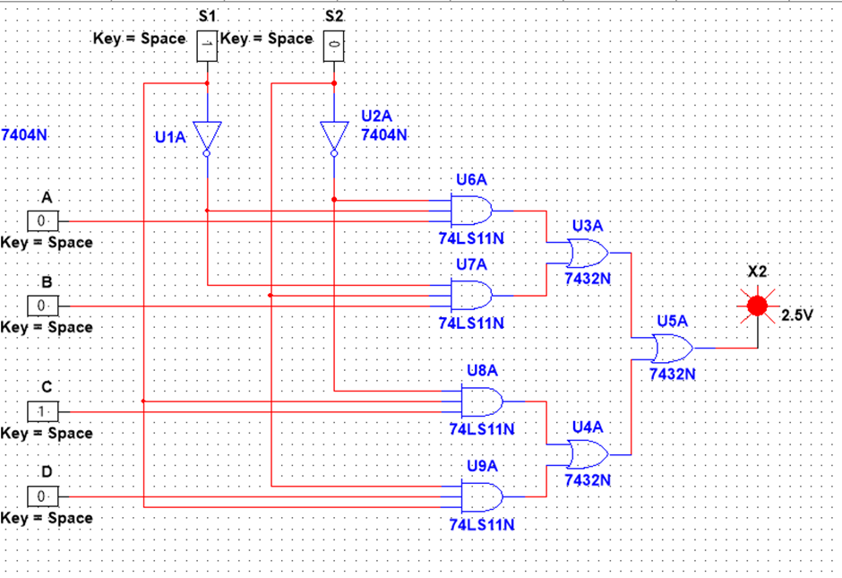
Aim: Design & implement a 4: 1 multiplexer using logic gate. Apparatus: Power supply IC – 7404, 7410, 7432, resistance 220 Ω. Observations: Truth Table: Input S1 S2 Output A 0 0 A B 0 1 B C 1 0 C D 1 1 D Result: Hence truth table verified.
4: 1 multiplexer using logic gate. Read More »
DIGITAL ELECTRONICS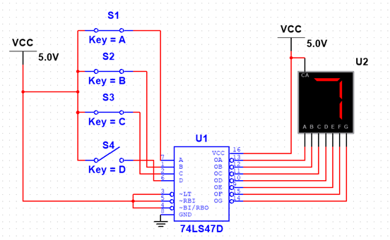
Aim: To design a seven-segment display Apparatus: IC 74LS47D , Seven segment Display , 5V(VCC),Resistance(1k) Circuit Diagrams: Result: seven segment display s designed and decimal number and 7 are verified
To design a seven-segment display Read More »
DIGITAL ELECTRONICS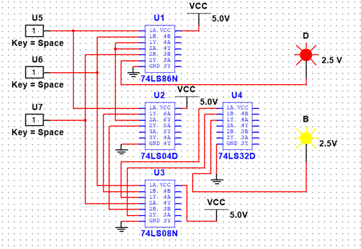
AIM Design a half and full subtractor. Apparatus Required : IC(74LS86N , 74LS04D , 74LS08N , 74LS32D) , DC power supply(5V) , 2 LEDs . Circuit Diagram : For Half subtractor – For Full subtractor – Result : Designing of Half and Full subtractor are done .
Design a half and full subtractor. Read More »
DIGITAL ELECTRONICS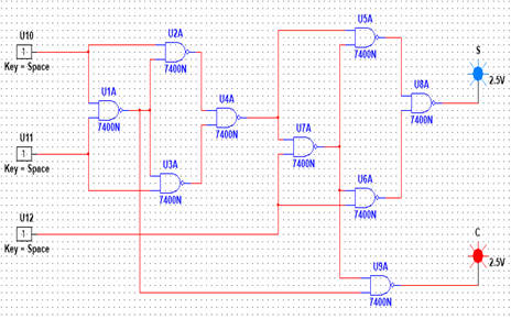
AIM: Design a Half and Full Adder Truth Table of Half Adder Inputs Outputs A B S (Sum) C (Carry) 0 0 0 0 0 1 1 0 1 0 1 0 1 1 0 1 Circuit Diagram: Truth Table of Full
Design a Half and Full Adder Read More »
DIGITAL ELECTRONICS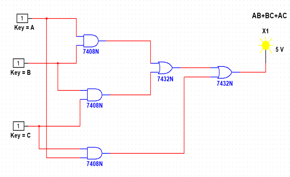
AIM: – To convert a Boolean expression into a large gate circuit and assemble it using logic gate IC’s. APPARATUS: – IC (7408 × 2), IC (7432 × 2), Breadboard, Connecting wires, LED. CIRCUIT DIAGRAM: – TRUTH TABLE : – A B C AB BC AC AB+BC AB+BC+AC 0 0 0 0 0
Boolean expression into a large gate circuit Read More »
DIGITAL ELECTRONICS