SEM 3

Experiment 8

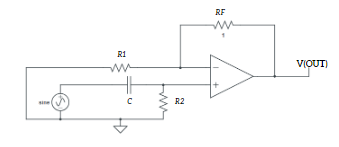
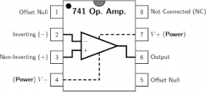
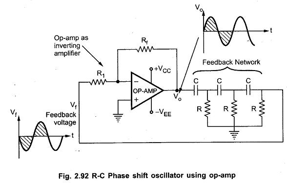
Aim: Designing a RC phase shift oscillator using op amp.Apparatus Required: 741 IC, Multimeter, CRO, Dual power supply (15-0-15 V), Resistors, Capacitor, and connecting wires.Theory:  A RC phase shift oscillator is a type of electronic oscillator circuit that generates sinusoidal signals. It utilises a network of resistors and capacitors (RC network) in a feedback loop […]

Experiment 8 Read More »

OP-AMP, SEM 3

Experiment 7

Aim: Designing a First Order High pass filter using op amp.Apparatus Required: 741 IC, Multimeter, CRO, Dual power supply (15-0-15 V), Resistors, Capacitor, and connecting wires.Theory: A first-order active high-pass filter is an electronic circuit designed to pass high-frequency signals while attenuating low-frequency signals. Similar to the low-pass filter, it consists of an active element,

Experiment 7 Read More »

OP-AMP, SEM 3, Uncategorized

Experiment 6

Aim: Designing a First Order Low pass filter using op amp.Apparatus Required: 741 IC, Multimeter, CRO, Dual power supply (15-0-15 V), Resistors, Capacitor, and connecting wires.Theory:  A first-order active low-pass filter is an electronic circuit designed to pass low-frequency signals while attenuating high-frequency signals. It consists of an active element, usually an operational amplifier (op-amp),

Experiment 6 Read More »

OP-AMP, SEM 3

Experiment 5

Aim: Designing a differentiator using an op amp and studying its frequency responses.Apparatus Required: 741 IC, Multimeter, CRO, Dual power supply (15-0-15 V), Resistors, Capacitors, and connecting wires.Theory: This operational amplifier circuit performs the mathematical operation of Differentiation, that is, it “produces a voltage output which is directly proportional to the input voltage’s rate-of-change with

Experiment 5 Read More »

OP-AMP, SEM 3

Experiment 4

Aim: Designing of an integrator using op amp and studying its frequency responses. Apparatus Required: 741 IC, Multimeter, CRO, Dual power supply (15-0-15 V), Resistors, Capacitors, and connecting wires. Theory: The Op-amp Integrator is an operational amplifier circuit that performs the mathematical operation of Integration, that is, we can cause the output to respond to

Experiment 4 Read More »

OP-AMP, SEM 3

Experiment 3

Aim: Designing of analog adder and subtractor.Apparatus Required: 741 IC, Multimeter, CRO, Dual power supply (15-0-15 V), Resistors, and connecting wires.Theory: An adder is a fundamental electronic circuit used to combine multiple input signals into a single output signal by performing the addition operation. In analog electronics, adders are commonly used in signal processing applications

Experiment 3 Read More »

OP-AMP, SEM 3

Experiment 2

Aim: Designing of an amplifier of given gain for an inverting and non-inverting configuration using an op amp. Apparatus Required: 741 IC, Multimeter, CRO, Dual power supply (15-0-15 V), Resistors, and connecting wires. Theory: An operational amplifier (“op amp”) is a direct-coupled, differential-input, high gain voltage amplifier, usually packaged in the form of a small

Experiment 2 Read More »

OP-AMP, SEM 3

Experiment 1

Aim: Study of op-amp characteristics: CMRR and Slew rate.Apparatus Required: 741 IC, Multimeter, CRO, Dual power supply (15-0-15 V), and connecting wires.Theory:  CMRR: CMRR stands for Common Mode Rejection Ratio. It measures the ability of an operational amplifier to reject common-mode signals, which are signals that appear simultaneously on both the inverting and non-inverting inputs.

Experiment 1 Read More »

OP-AMP, SEM 3

OP-AMP

Op-amp block diagram Op-amp ic introduction and pin diagram  The pin configur ation of the IC 741 operational amplifier is shown below. The op amp 741 pin diagram and the functionality of each pin are explained clearly in the below section. IC 741 Pin Diagram Power Supply Pins: Pin 4 and 7 Pin 4 and

OP-AMP Read More »

SEM 3
Scroll to Top