Communication Electronics
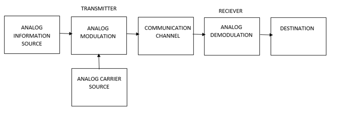
The word Communication can be broadly understood as transfer of information. The information can be an Analog signal or a Digital signal. For it to move from a Source to a Destination several processes are required.
Few important terms
Baseband Signal: It is message signal in its original form in amplitude as well as frequency.
Base band Transmission: When the baseband signals (original form) are transmitted. However, because of its limitations only Broadband Transmission is used.
Broadband Transmission: When thebaseband signal is changed (modulated) to be suitable for transmission
Need for Modulation:
- Reduction in the height of the antenna
- Avoid mixing of signals
- Increases the range of communication
- Multiplexing is possible
Types of Modulation
Analog
- Amplitude Modulation
- Angle Modulation
- Frequency Modulation
- Phase Modulation
Digital
- Pulse Code modulation
- Delta Modulation
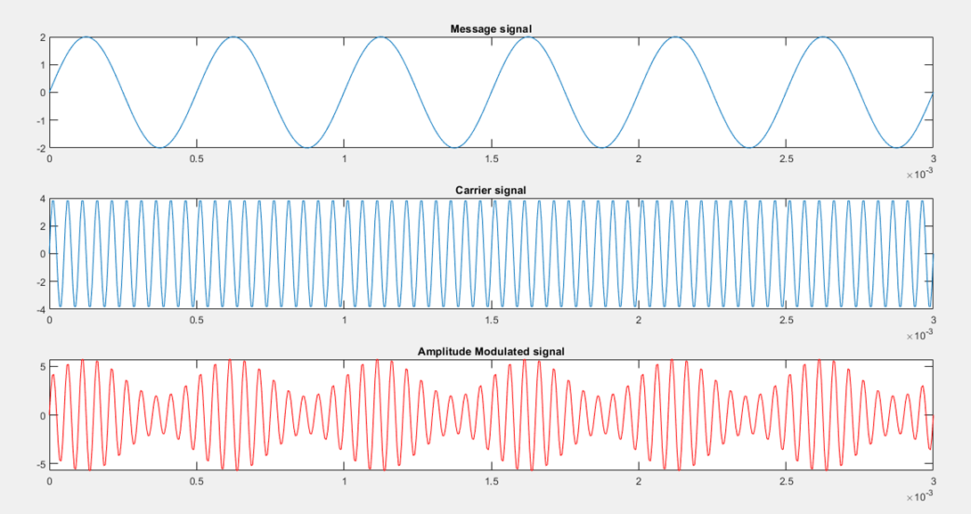
For the process of modulation two signals are required one is high frequency signal called the Carrier and the other is the low frequency signal called the Baseband (Message) Signal.
When the amplitude of the carrier is modified in accordance with the baseband signal it is known as Amplitude modulation. The diagram shows the Baseband, Carrier and Amplitude modulated waveforms
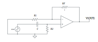
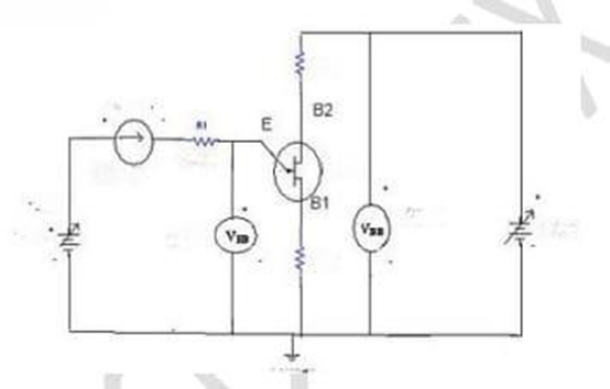
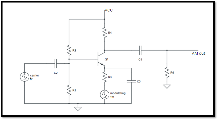
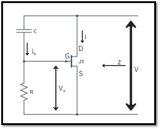
The basic circuit used for the generation of Amplitude Modulation is as follows
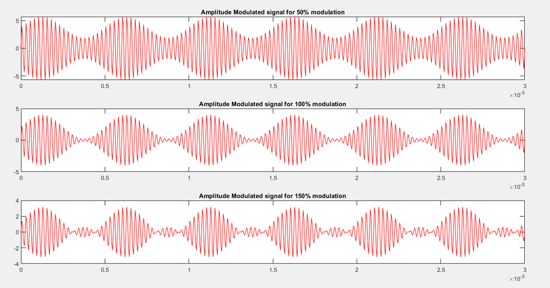
The above diagram shows the waveform for the amplitude modulated wave for three different values of modulation index.
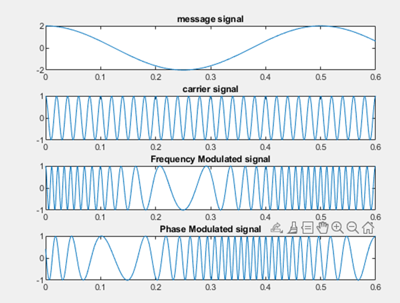
Angle Modulation
Both Frequency and Phase Modulation are clubbed under the same heading of Angle Modulation because a change in one leads to a change in the other i.e. a change in frequency leads to a change in the phase and vice versa; a change in phase leads to a change in frequency.
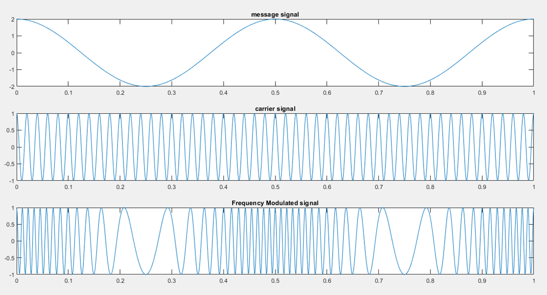
Frequency Modulation
When there is a change in the carrier frequency in accordance with the base band signal it is known as Frequency Modulation.
Phase Modulation
When the baseband signal is to vary the angle of phase Lead or Lag it is known as Phase Modulation
Pulse Modulation
For the AM FM and PM discussed earlier the carrier is Sinusoidal Signal. However, in Pulse modulation the Carrier is in form of Pulses instead of a Sinewave.
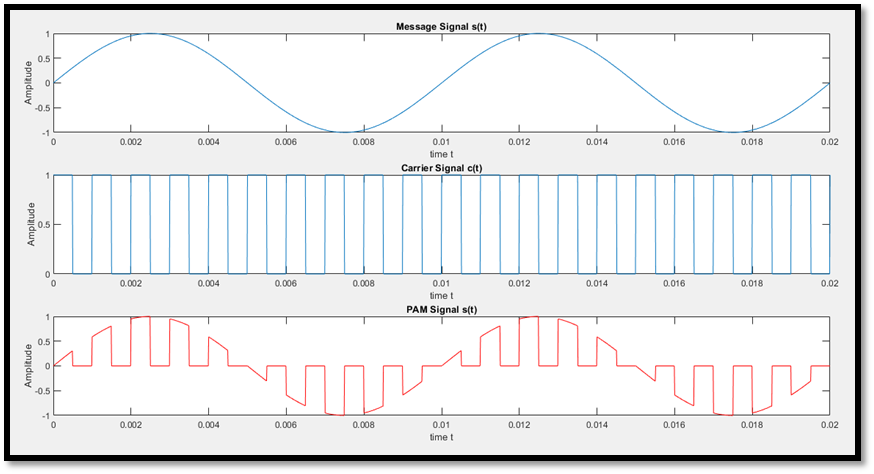
When the amplitude of the Pulses is varied in accordance with the message signal it is PAM( Pulse Amplitude Modulation).
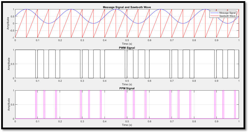
When the width of the Pulses is varied in accordance with the message signal it is PWM( Pulse Width Modulation).
When the position of the Pulses is varied in accordance with the message signal it is PPM( Pulse Position Modulation)
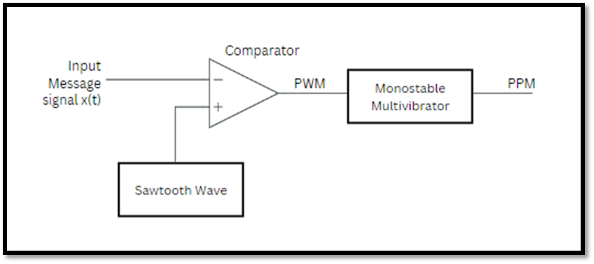
PWM and PPM signals:
Circuit for generation of PAM signal
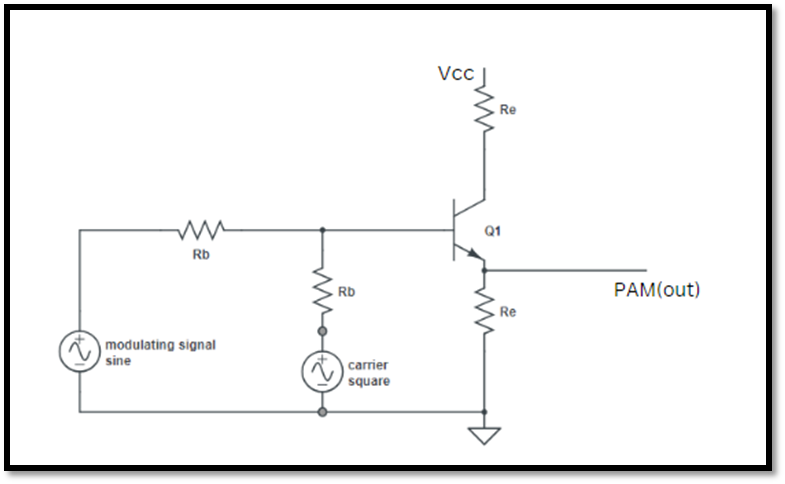
PAM signal: