Cathode Ray Oscilloscope/ Digital Storage Oscilloscope
An oscilloscope is a test instrument which allows us to look at the ‘shape’ of electrical, signals by displaying a graph of voltage against time on its screen. It is like a voltmeter with the valuable extra function of showing how the voltage varies with time.
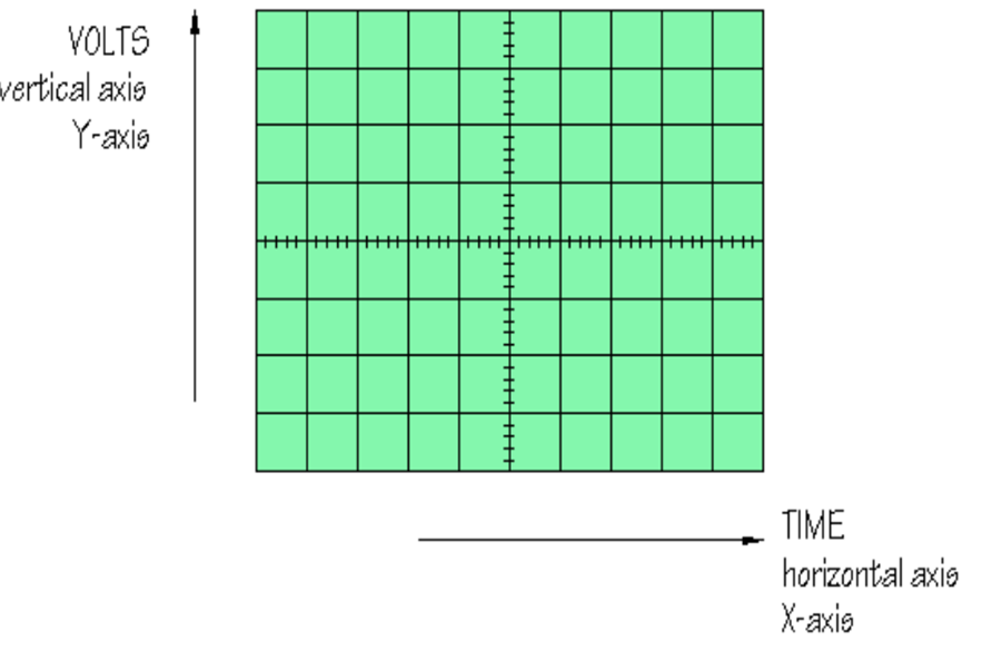
A graticule with a 1cm grid enables us to take measurements of voltage and time from the screen.
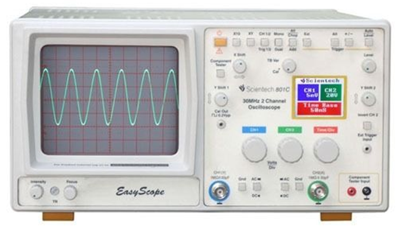
Figure: Front Panel of CRO
Procedure
- Switch on the oscilloscope to warm up (it takes a minute or two).
- Do not connect the input lead at this stage.
- Set the AC/GND/DC switch (by the Y INPUT) to DC.
- Set the SWP/X-Y switch to SWP (sweep).
- Set Trigger Level to AUTO.
- Set Trigger Source to INT (internal, the y input).
- Set the Y AMPLIFIER to 5V/cm (a moderate value).
- Set the TIMEBASE to 10ms/cm (a moderate speed).
- Turn the timebase VARIABLE control to 1 or CAL.
- Adjust Y SHIFT (up/down) and X SHIFT (left/right) to give a trace across the middle of the screen, like the picture.
- Adjust INTENSITY (brightness) and FOCUS to give a bright, sharp trace.
- A calibration point is used to calibrate the CRO. It gives a steady square wave at a particular set frequency and voltage. It allows the accurate scaling of the trace. The standard calibration signal is 0V-2V at 1KHz.
After connecting the oscilloscope to the circuit you wish to test, set the controls to obtain a clear and stable trace on the screen. Most oscilloscopes have a BNC socket for the y input and the lead is connected with a push and twist action.
Control Knobs:
- The Y AMPLIFIER (VOLTS/CM) control determines the height of the trace. Choose a setting so the trace occupies at least half the screen height, but does not disappear off the screen.
- The TIMEBASE (TIME/CM) control determines the rate at which the dot sweeps across the screen. Choose a setting so the trace shows at least one cycle of the signal across the screen. Note that a steady DC input signal gives a horizontal line trace for which the timebase setting is not critical.
- The TRIGGER control is usually best left set to AUTO.
- AC/GND/DC switch: The normal setting for this switch is DC for all signals – including AC signals! Switching to GND (ground) connects the y input to 0V and allows you to quickly check the position of 0V on the screen. Switching to AC inserts a capacitor in series with the input to block out any DC signal present and pass only AC signals.
- Position: Controls horizontal position of trace on screen.
- DUAL BUTTON: The oscilloscope has a capability to display both channel signals on the screen at the same time. This is known as DUAL MODE.
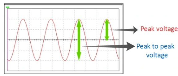
Measurement of peak-to-peak voltage and peak voltage:
- To measure the ac. voltage of sinusoidal waveform. The input ac. signal is applied from the signal generator to a channel of CRO. The voltage/div switch (Y-plates) and time base switch (X-plates) are adjusted such that a steady picture of the waveform is obtained on the screen.
- The vertical height (L) i.e. peak-to-peak height is measured. When this peak-to-peak height (L) is multiplied by the voltage/div. (voltage deflection sensitivity ‘n’) we get the peak-to-peak voltage (2Vo).
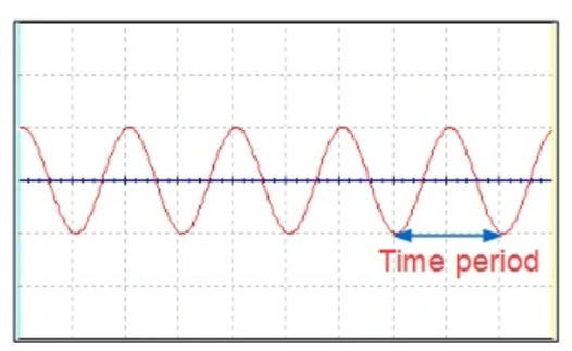
MEASUREMENT OF FREQUENCY
Using time-period:
From the trace the time period of the input signal is equal to ‘t’ times the value of time/div setting.
Suppose that the time period of the input signal is T.
Then, the frequency of the signal =1/T
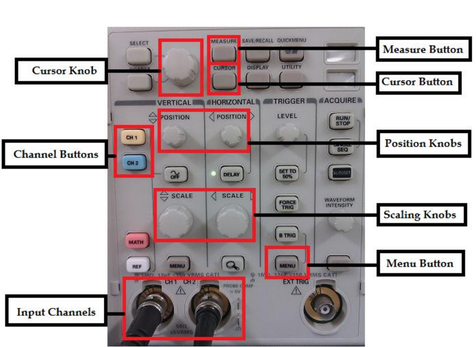
Digital Storage Oscilloscope Front Panel Contro