AIM-
To study the VI characteristics of DIAC with positive biasing and plot the curve between V and I.
APPARATUS-
NV6531 Diac Characteristic Trainer, 2mm Patch Cord
THEORY-
The diac is a two-terminal device that has three semiconductor layers. It is a bidirectional diode,
i.e. it can be made to conduct in either direction. This is just like a TIRAC without a gate terminal. The switching from OFF to ON state can be achieved by simply exceeding the avalanche breakdown in either direction..
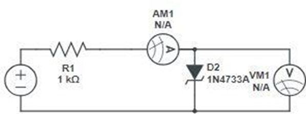
CIRCUIT DIAGRAM-

PROCEDURE-
POSITIVE BIASING
- Make the connections as same as the circuit diagram.
- Connect the +35V DC supply to the circuit by connecting point 1 with point 4 with the help of a patch cord.
- Rotate the potentiometer P1 in the fully anti-clockwise direction.
- Now connect point 2 with point 8 to make grounds common.
- Connect the voltmeters across the DIAC. For that connect the posiitve terminal of voltmeter with the point 7 and connect the negative terminal with point 8.
- Now connect the Ammeter to the point 5 and negative terminal to the point 6.
- Connect the mains cord to the trainer and switch on the supply.
NEGATIVE BIASING
- Connect -35V DC Supply to the circuit by connecting the point 3 and point 4.
- Repeat the process from steps 3-7.
- Now plot the VI curve for taken readings.
OBSERVATION TABLE-
| POSITIVE BIASING | NEGATIVE BIASING | ||
| DIAC Voltage (in V) | DIAC Current (in mA) | DIAC Voltage (in V) | DIAC Current (in mA) |
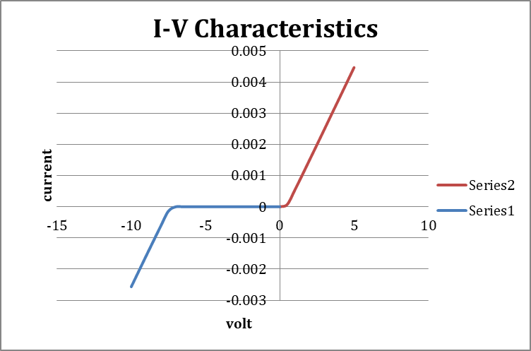
RESULT-
VI characteristics of DIAC in both positive and negative bias are obtained.
In forward bias, the current increases after V, and in the reverse bias, the current increases after – V.
PRECAUTIONS-
- Connections should be tight.
- Avoid double connection.