Aim: Designing of an amplifier of given gain for an inverting and non-inverting configuration using an op amp.
Apparatus Required: 741 IC, Multimeter, CRO, Dual power supply (15-0-15 V), Resistors, and connecting wires.
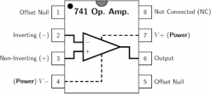
Theory: An operational amplifier (“op amp”) is a direct-coupled, differential-input, high gain voltage amplifier, usually packaged in the form of a small integrated circuit. An operational amplifier is basically a three-terminal device which consists of two high impedance inputs. One of the inputs is called the Inverting Input, marked with a negative or “minus” sign, (–). The other input is called the Noninverting Input, marked with a positive or “plus” sign (+). A third terminal represents the operational amplifier’s output port which can both sink and source either a voltage or a current. In a linear operational amplifier, the output signal is the amplification factor, known as the amplifier’s gain (A).
OPEN LOOP CONFIGURATIONS: The term “open loop” means that there are no feedback components used around the amplifier so the feedback path or loop is open.
CLOSED LOOP CONFIGURATIONS: Closing the open loop by connecting a resistive or reactive component between the output and one input terminal of the op-amp greatly reduces and controls this open-loop gain. Op-amps can be connected into two basic configurations, Inverting and Noninverting.
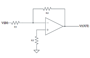
Inverting Amplifier: The inverting operational amplifier is basically a constant or fixed-gain amplifier producing a negative output voltage as its gain is always negative. In the Inverting Amplifier circuit, the operational amplifier is connected with feedback to produce a closed loop operation.
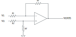
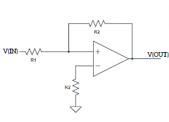
Non-Inverting Amplifier: In the non-inverting operational amplifier configuration, the input voltage signal, (Vin) is applied directly to the non-inverting (+) input terminal which means that the output gain of the amplifier becomes “Positive” in value in contrast to the “Inverting Amplifier” circuit. The result of this is that the output signal is “in-phase” with the input signal.
Designing Steps:
Inverting Amplifier: A = 𝑅𝑓 / 𝑅𝑖
Non-Inverting Amplifier: A = 1 + 𝑅𝑓 / 𝑅𝑖
Circuit Diagram:
Inverting Amplifier
Non Inverting Amplifier:
Precautions:
- Do not connect more than 15 v DC supply
- Always check the Dual power supply with a multimeter before connecting it to the circuit
- Connect an input supply such that the corresponding output remains within the range +14 to -14 volts
- Connections should be neat and tight.