Aim: Designing of analog adder and subtractor.
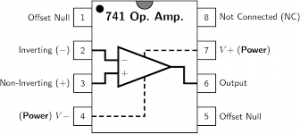
Apparatus Required: 741 IC, Multimeter, CRO, Dual power supply (15-0-15 V), Resistors, and connecting wires.
Theory: An adder is a fundamental electronic circuit used to combine multiple input signals into a single output signal by performing the addition operation. In analog electronics, adders are commonly used in signal processing applications where it is necessary to sum two or more analog voltages or currents.
There are two main types of adders: inverting adders and non-inverting adders.
- Inverting Adder:
In an inverting adder configuration, the output signal is the negative sum of the input signals. It uses an operational amplifier (op-amp) with a negative feedback configuration. The input signals are applied to the inverting (-) input terminal of the op-amp through input resistors, and the output is fed back to the inverting input through a feedback resistor.
- Non-Inverting Adder:
In a non-inverting adder configuration, the output signal is the positive sum of the input signals. It also uses an op-amp but with a non-inverting (+) input terminal configuration. The input signals are applied to the non-inverting input terminal through input resistors, and the output is fed back to the inverting input through a feedback resistor.
Subtractor:
A subtractor is another essential electronic circuit used to calculate the difference between two input signals. It can be implemented using op-amps and resistors. Similar to adders, subtractors can also be classified into inverting and non-inverting configurations.
- Inverting Subtractor:
In an inverting subtractor configuration, the output signal is the negative difference between the two input signals. It uses an op-amp with a negative feedback configuration. One input signal is applied to the non-inverting input terminal, while the other input signal is applied to the inverting input terminal through an input resistor. The output is fed back to the inverting input through a feedback resistor.
- Non-Inverting Subtractor:
In a non-inverting subtractor configuration, the output signal is the positive difference between the two input signals. It uses an op-amp with a non-inverting input terminal configuration. One input signal is applied to the inverting input terminal, while the other input signal is applied to the non-inverting input terminal through an input resistor. The output is fed back to the inverting input through a feedback resistor.
Designing Steps for Adders and Subtractors:
The gain (A) of the adder or subtractor circuit determines the scaling factor between the input signals and the output signal. The formula for calculating the gain depends on the specific configuration of the circuit.
For Inverting Adder/Inverting Subtractor:
The formula for the gain (A) is given by:
Based on the desired gain and input signal levels. Typically, the resistor values are selected to achieve the desired gain while ensuring stability and proper operation of the circuit. Additionally, the choice of resistor values may also depend on factors such as input impedance, output impedance, and power supply voltage.
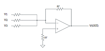
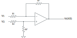
Circuit Diagrams:
- ADDER
- SUBTRACTOR
Precautions:
- Do not connect more than 15 v DC supply
- Always check the Dual power supply with a multimeter before connecting it to the circuit
- Connect an input supply such that the corresponding output remains within the range +14 to -14 volts
- Connections should be neat and tight.