Aim- Measurement of capacitance by De-Sauty’s Bridge.
Apparatus- De-Sauty Bridge set up, Headphones, AC Supply, Wires.
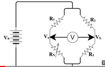
Theory- The De Sauty Bridge consists of four arms, each containing a capacitor and a resistor. The arms are arranged in a diamond configuration, with a voltage source applied across one diagonal. One of the capacitors is the unknown capacitor Cx, while
the other three capacitors are known C1, C2 and C3.
The bridge is considered balanced when there is no audio output detected across the headphones. This balance condition is achieved when the impedance of the headphones matches the known impedance or resistance values in the other arms of the bridge.
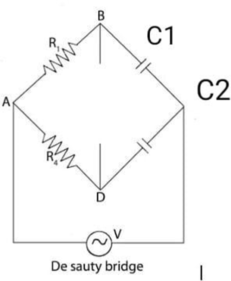
Circuit Diagram-
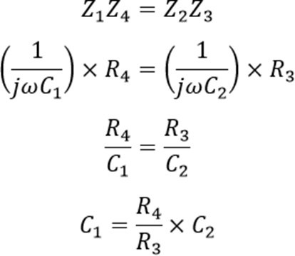
Formula used:-
Procedure-
- Connect AC Supply 1kHz with terminals marked supply. Unknown capacitor with terminals marked unknown and head phones with the terminals marked detector.
- Set the resistance dial R1 to some value, say 1000 Ω and set standard capacitor C1 to the 0.1µF position.
- Now adjust decade resistance dial R1 to minimize the sound in the head phones.
- Note value R1, R2 and C1 and calculate the unknown capacitance C2 using formula.
- Repeat the above steps on different values of resistance R1 and C1.
Observation Table-
| C2 | ||
| R2 | ||
| R1 | ||
| C1 |
Calculate for different values of resistor and capacitor.
Result- The capacitor C1 is about __µF, C2 is about __µF, C3 is about __µF and C4 is about __µF.
Precautions-
- Make sure all the connections are tight.
- If there is found no sound in head phone for a range of Q resistance then total range should be noted and mean of them should be taken.