Aim: Designing of an integrator using op amp and studying its frequency responses.
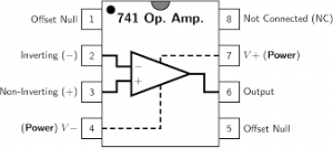
Apparatus Required: 741 IC, Multimeter, CRO, Dual power supply (15-0-15 V), Resistors, Capacitors, and connecting wires.
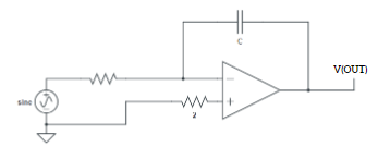
Theory: The Op-amp Integrator is an operational amplifier circuit that performs the mathematical operation of Integration, that is, we can cause the output to respond to changes in the input voltage over time as the op-amp integrator produces an output voltage which is proportional to the integral of the input voltage.
CIRCUIT:
Precautions:
- Do not connect more than 15 v DC supply
- Always check the Dual power supply with a multimeter before connecting it to the circuit
- Connect an input supply such that the corresponding output remains within the range +14 to -14 volts
- Connections should be neat and tight.
Note:
Drawbacks in ideal integrator:
1. Bandwidth is very small and used for only a small range of input frequencies.
2. For dc input (f = 0), reactance of capacitance, Xc is infinite. Because of this op-amp goes into open loop configuration.In open loop configuration the gain is infinite and hence the small input offset voltages are also amplified and appear at output as error. This is referred to as false triggering and must be avoided.
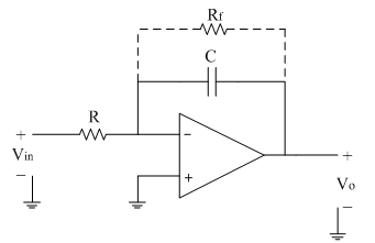
Due to all such limitations, an ideal integrator needs to be modified. This modified integrator is referred to as a practical integrator.
The limitations of an ideal integrator can be minimised in the practical circuit by adding resistor Rf in parallel with capacitor C this Rf avoids op-amp going into open loop configuration at low frequencies.
The practical integrator circuit is shown below.
1. Bandwidth of practical integrator fa is higher than BW of an ideal integrator.
2. DC gain (at f=0) is |Rf/R| which is typically ≥10.
3. For better integration fb≥10fa.
4. For proper integration Time period T of input signal ≥Rf C