Aim– Measurement of Inductance by Anderson’s Bridge.
Material Required– Anderson Bridge Trainer Kit, Wires
Theory– The Anderson bridge is a bridge circuit used for measuring unknown resistances, especially those with high values. The bridge is balanced when the ratio of the resistances in the adjacent arms is equal.
Circuit Diagram-
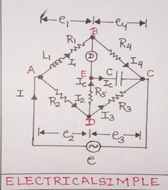
Formula used and derivation –

Procedure-
DC BALANCE
- Connect DC Supply with the terminals marked supply, unknown inductance with the terminals marked unknown, and a galvanometer with the terminals marked detector.
- Now adjust the decade resistance dial R to find out the balance point in the galvanometer and also use resistance dial S for fine adjustment.
- Note the value R.
AC BALANCE
- After DC Balance without disturbing the position of the bridge. Connect the AC Supply 1kHz instead of DC Supply and head phone instead of galvanometer.
- Now adjust the resistance dial R to minimize the sound in the head phones..
- Note the value of R and calculate the value of unknown inductance by using the given formula.
- Repeat the experiment with another value of C.
Observation Table-
Combination 1:-
| S.No. | L | C | R(in Ω) | r(in Ω) | P(in Ω) | Q (in Ω) |
| 1 | ||||||
| 2 |
Repeat for other combinations.
Precautions:-
- Make sure all the connections are tight.
- To avoid inductive effect short straight wires should be used.