Aim: Designing a First Order Low pass filter using op amp.
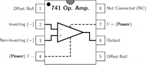
Apparatus Required: 741 IC, Multimeter, CRO, Dual power supply (15-0-15 V), Resistors, Capacitor, and connecting wires.
Theory:
A first-order active low-pass filter is an electronic circuit designed to pass low-frequency signals while attenuating high-frequency signals. It consists of an active element, usually an operational amplifier (op-amp), combined with passive components such as resistors and capacitors. This type of filter is called “first-order” because it provides a roll-off rate of -20 dB/decade or -6 dB/octave
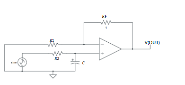
The input signal (Vin) is applied to the inverting (-) input terminal of the op-amp through resistor R1. The non-inverting (+) input terminal is usually connected to the ground (GND) or a reference voltage. The resistor R1 provides input impedance to the circuit. The output signal (Vout) is taken from the output terminal of the op-amp.
The resistor R1 is connected in series with the capacitor C1, forming a low-pass filter network. At low frequencies, the impedance of the capacitor is high, allowing the signal to pass through to the output relatively unimpeded. As the frequency increases, the impedance of the capacitor decreases, causing the voltage across it to drop. This effect attenuates high-frequency signals and passes low-frequency signals to the output.
The cutoff frequency (fc) of the filter is the frequency at which the output voltage is attenuated by -3 dB (approximately 70.7% of the input voltage). It is determined by the values of the resistor (R1) and capacitor (C1) according to the formula:
fc = 1/(2piRC)
Advantages:
- Flexibility: The cutoff frequency of the filter can be easily adjusted by changing the values of the resistor and capacitor.
- Low Output Impedance: The output impedance of the op-amp is typically low, providing a stable output signal.
- High Accuracy: Active filters offer higher accuracy and precision compared to passive filters
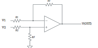
Circuit Diagram:
Precautions:
- Do not connect more than 15 v DC supply
- Always check the Dual power supply with a multimeter before connecting it to the circuit
- Connect an input supply such that the corresponding output remains within the range +14 to -14 volts
- Connections should be neat and tight.