Aim:
Verification of Maximum Power Transfer Theorem
Components and Equipment Required:
Beadboard, multimeter, connecting wires, DC power supply, resistor, resistance box
Theory:
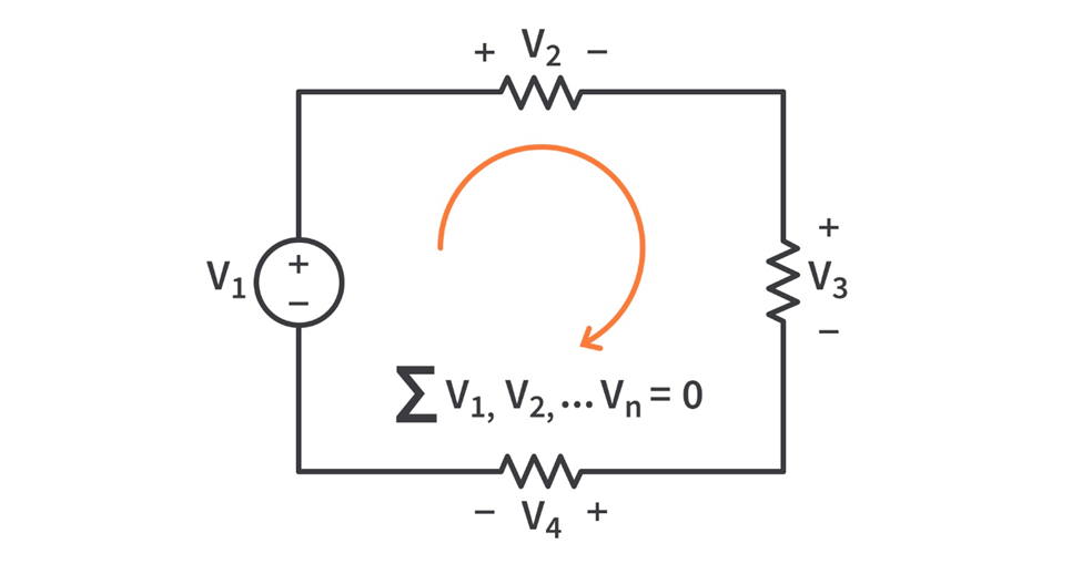
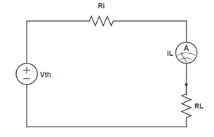
According to Maximum Power Transfer Theorem, a linear two terminal network consisting of a voltage source and resistance will transfer maximum power into a load connected between its two terminal when the load resistance is equal to the Thevenin’s resistance Rth of the network, that is when RL =Rth.
Formula used:

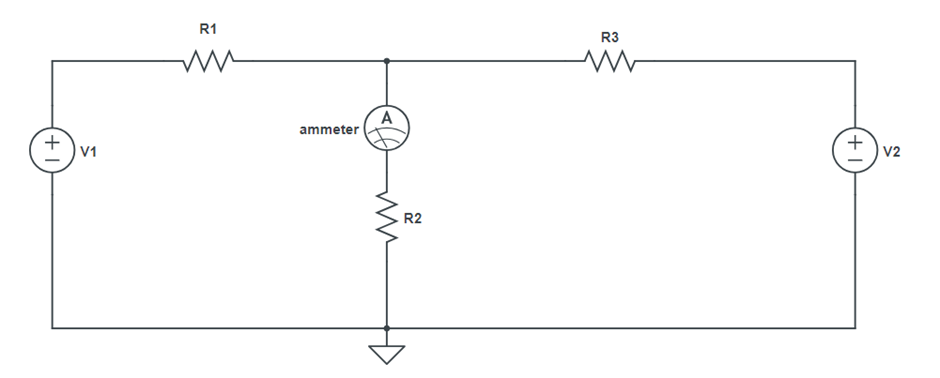
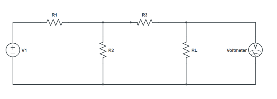
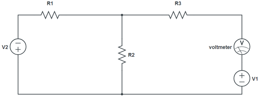
Circuit Diagram:
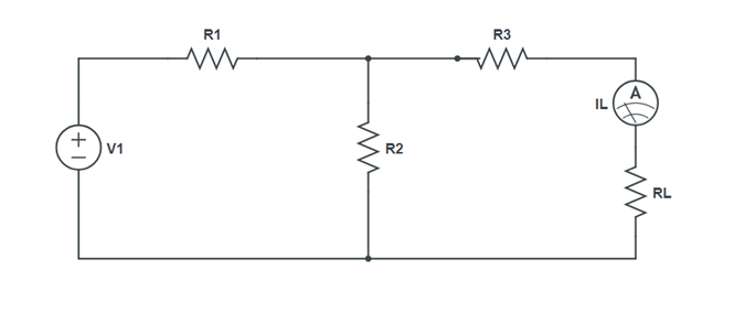
Procedure:
- Make circuit on breadboard with a resistance box as RL. Connect digital multimeter cross RL to measure the load Voltage VL.
- Take out voltage of resistance from RL and measure the load voltage VL across it.
- Measure and note down the load voltage VL by choosing RL at regular interval
- Calculate power PL for each values of RL.
- Plot PL as function of RL
Observation Table:
| RL (Ω) | VL (V) | PL (Watt) | PL (mWatt) |
Result:
The output power PL is maximum for RL=Rth.Hence, the Maximum Power Transfer Theorem is verified.
Precautions:
- The output voltage of the power supply should remain constant during the experiment.
- The internal resistance of the power supply, if any, is neglected.
- The power supply should be switched off while making or breaking the circuit