Aim:
Verification of Norton’s Theorem
Components and Equipment Required:
Variable power supply , 3 resistors, resistance box, constant current source, connecting wires
Theory:
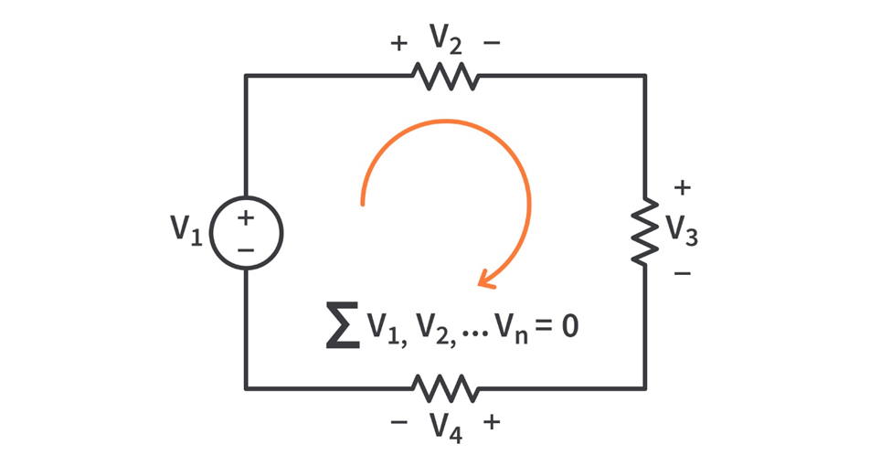
Norton’s theorem states that a linear two-terminal circuit can be replaced by an equivalent circuit consisting of a current source IN in parallel with a resistor RN, where IN is the short-circuit current through the terminals and RN is the input or equivalent resistance at the terminals when the independent sources are turned off.
The Norton’s equivalent current IN is the short circuit current between the terminals when all voltage sources in network are short-circuited and all current sources are open circuited.
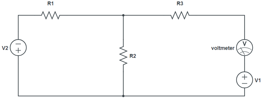
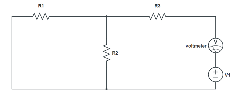
Circuit Diagram:
Procedure:
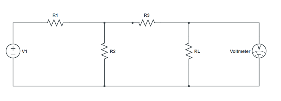
- Perform steps, make the circuit on breadboard with a resistance box as RL and a multimeter to measure voltage VL across RL. Set output of power supply.
- Take out resistance from the resistance box and note down VL as measured by Multimeter.
- Vary RL and note down the corresponding value of VL.
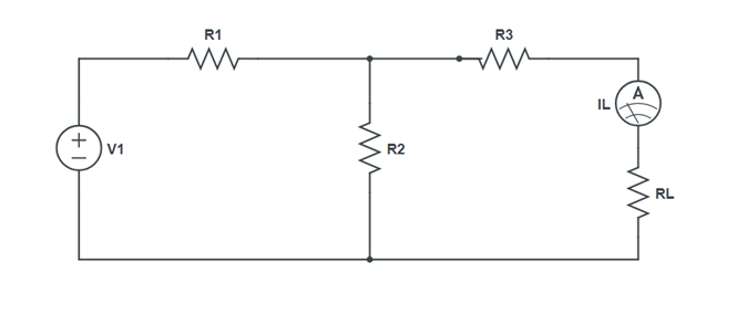
- Note down the load current IL=VL/RL for each value of RL.
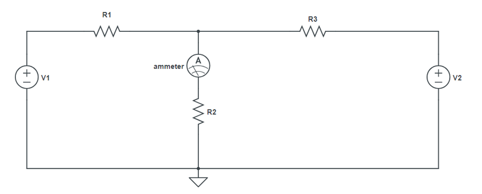
- Remove RL, connect ammeter between terminal A and B and measures short circuit current ISC. This is the Norton equivalent current IN.
- Remove RL from the circuit and replace the power supply by a short circuit, measure the resistance between A and B directly with the multimeter.
- Make the Nortons equivalent circuit, adjust the current from the current source. Take out the resistance and measure the lower resistance IN the multimeter connected in series with a RL
- Vary RL and note down its corresponding values of I1.
- Compare the values of load current in the original circuit and in the Norton’s equivalent circuit for each value of RL.
- When current source is not available, connect a power supply in series with a variable resistance and milliammeter in place of the current source.
Observation Table:
Original circuit Norton’s equivalent
|
R (Ω) |
VL (V) | IL (mA) | VN | IN |
Result:
The measured values of the load current and load voltage in the original circuit match the corresponding values in the Norton’s equivalent circuit.
Precautions:
- The current in the circuit should remain constant for all observations
- Set the voltmeter point at 0.
- Check connections properly