Aim: Designing a RC phase shift oscillator using op amp.
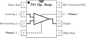
Apparatus Required: 741 IC, Multimeter, CRO, Dual power supply (15-0-15 V), Resistors, Capacitor, and connecting wires.
Theory:
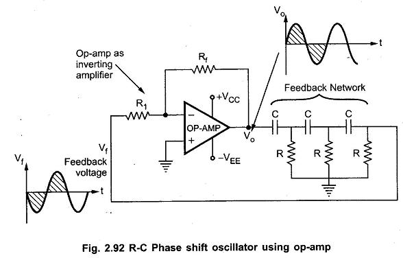
A RC phase shift oscillator is a type of electronic oscillator circuit that generates sinusoidal signals. It utilises a network of resistors and capacitors (RC network) in a feedback loop along with an operational amplifier (op-amp) to produce a stable oscillating output. This type of oscillator is called a “phase shift” oscillator because it relies on the phase shift introduced by the RC network to achieve oscillation.
Working Principle:
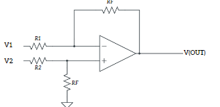
The input signal (Vin) is applied to the inverting (-) input terminal of the op-amp through resistor R2. The non-inverting (+) input terminal is usually connected to the ground (GND) or a reference voltage. The resistors R1, R2, and R3 along with the capacitors C1, C2, and C3 form a phase-shift network in the feedback loop.
The phase shift introduced by each RC section in the network causes the feedback signal to be shifted in phase as it travels through the network. The total phase shift around the feedback loop is set to 360 degrees (or 0 degrees) at the desired oscillation frequency. This phase condition is necessary for sustained oscillations to occur.
Frequency of Oscillation:
The frequency of oscillation (fo) of the RC phase shift oscillator is determined by the time constant of the RC network. It can be calculated using the formula:
fo = 1/(2piRC)
Circuit Diagram:
Precautions:
- Do not connect more than 15 v DC supply
- Always check the Dual power supply with a multimeter before connecting it to the circuit
- Connect an input supply such that the corresponding output remains within the range +14 to -14 volts
- Connections should be neat and tight