Aim:
To design RC low pass filter and study its frequency response.
Apparatus Required:
- Bread Board
- CRO (Cathode Ray Oscilloscope)
- Resistance
- Capacitor
- Connecting Wires and CRO Probes
- Function Generator
Theory:
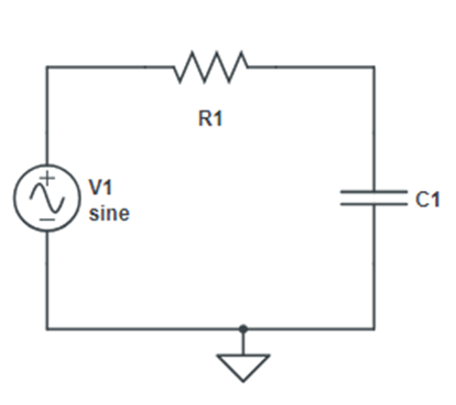
A filter is a circuit that passes a specific range of frequencies while rejecting other frequencies. A passive filter consists of passive circuit element such as capacitor, inductor and resistor. A typical low pass filter is formed when the output of an RC circuit is taken off the capacitor as shown in the circuit diagram.
The transfer function is:
H (ω) =VO /VI = (1/jωC) / [R+ (1/jωC)]
H (ω) = 1/1+jωRC
This figure shows the plot of |H (ω)|, along with ideal characteristics.
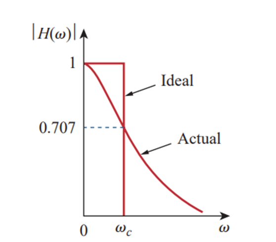
The half-power frequency, which is equivalent to the corner frequency on the Bode plots but in the context of filters is usually known as the cutoff frequency is obtained by setting the magnitude H (ω) of equal to 1/ (2)1/2 thus,
H (ωC) = 1/ [1+ (ω2R2C2)] 1/2 = 1/ (2)1/2
| ωC = 1/RC |
The cutoff frequency is also called rolloff frequency
A lowpass filter is designed to pass only frequencies from dc up to the cutoff frequency
Formula Used:
ωC = 1/RC
we know,
ωC = 2πfC
Thus, for calculating the value of cutoff frequency the formula is:
| fC = 1/2πRC |
In terms of capacitor when resistor is taken as a constant value:
| C = 1/2πRfC |
Circuit Diagram:
Procedure:
- Set up the circuit as shown in the circuit diagram taking the output on the capacitor. The input for the filter is taken from the output of the function generator. The input of the filter is also connected to channel 1 and the output is connected to channel 2 of CRO.
- Vary the frequency of the input signal over a wide range. Note the VOUT for each frequency and calculate the corresponding gain.
- Plot the values of gain versus frequency graph
Observation Table:
| Sr.No. | Frequency | VIN | VOUT | VOUT/VIN |
Result:
A low pass filter for a given cut-off frequency is designed successfully.
Precautions:
- Check connections twice.
- Make the circuit neat and clean.