Function generator
Function Generator is basically a signal generator that produces different types of waveforms at the output. It has the ability to produce waveforms such as sine wave, square wave, a triangular wave, sawtooth wave etc. An adjustable frequency range is provided by the function generator which is in the range of some Hz to several 100KHz.
The various waveforms generated by the function generator are suitable for various applications. It provides adjustment of wave shape, frequency, magnitude and offset but requires a load connected before adjustment.
Block Diagram & Its Working
This section explains the block diagram of the function generator along with its working. Below is the block diagram picture:
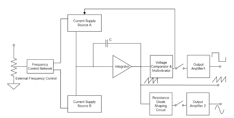
Block Diagram
For a function generator construction, a frequency controlling network is used where is frequency is regulated by the change in the current’s magnitude level. An integrator is used where this is driven by two current sources represented as current source ‘A’ and current source ‘B’ and both these current sources are controlled by the frequency regulated voltage.
A constant current is provided to the integrator section using current source ‘A’ and because of this integrator’s voltage level increases in proportion with time. The below equation determines the linear increase in the output signal voltage.
Vout = [-1/C] ʃt0 i dt
Ang change in the current level either increasing or decreasing correspondingly changes the output voltage slope and thus regulates the frequency level.
Also, in the function generator block diagram, a voltage comparator, and multi-vibrator device is used where this triggers a change in the phase of the output voltage at the integrator at the previously defined peak level. As because of the change in phase, the current supply from source ‘A’ stops and source ‘B’ starts to supply power to the integrator. Because the source ‘B’ providing power, the integrator generates a reverse current. This reverse current results in a drop in the output of the integrator proportionally with time. Before this time, when the output reaches the maximum level, the comparator again alters its state and gets back to the current source ‘A’.
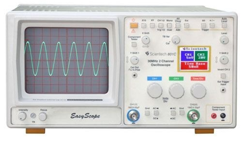
Therefore, the integrator output is a triangular waveform where its frequency is based on the current supply of both the current sources. And the comparator output is a square waveform. The circuit also has a resistance diode network that modifies the triangular wave slope having a minimum distortion of nearly 1%. And the amplifier at the output stage assists in providing two waveforms, thus the resultant signal is observed using an oscilloscope.
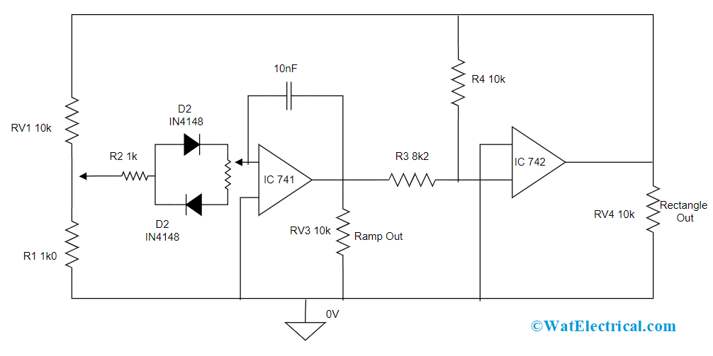
Function Generator Circuit
This is the function generator working explaining with the block diagram.
Abilities of Function Generator
As discussed, function generators hold the capability of generating multiple waveforms, and those are explained as below:
The other feature of a function generator is its ability to offer variation in the shape of the wave, magnitude, offset, and frequency whereas a load is necessary before doing the adjustment.
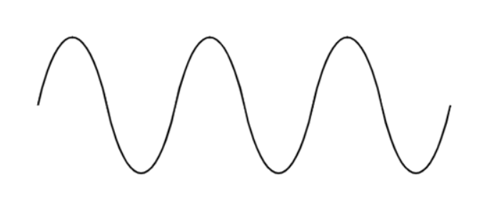
A.
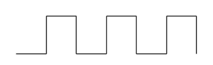
B.
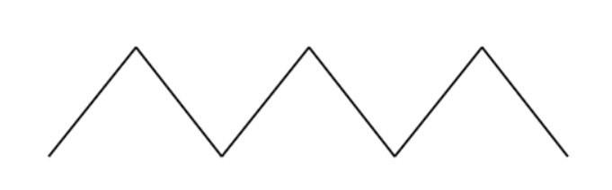
C.
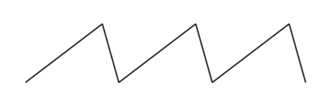
D.
Signal Waveforms: A. Sine, B. Square, C. Triangular, D. Saw-tooth
Controlling Aspects of Function Generator
Apart from providing the selection of fundamental waves, a function generator can even provide multiple controlling options and those are discussed below:
- DC offset value – This helps in varying the signal voltage corresponding to ground level.
- Frequency – The frequency control in the function generator varies the basic frequency level where the wave repeats, and this is not dependent on the type of waveform.
- Duty cycle – This controlling option alters the high and low voltage ratio timings in the sine wave which means altering the square wave having a 1:1 duty cycle to another type of waveforms such as triangles having the same level of rising and fall timings.
- Selection of waveform – This controlling option allows to a selection of various types of fundamental waveforms which are sine, triangular and square waveforms.
- Triggering input – This is the input terminal used for counting the frequency
- Adjustment knob – This control sets the parameter chosen by other buttons in the device
- Adjustment for amplitude-offset – This is the knob that helps in adjusting either the DC offset voltage or amplitude level of the signal
- And these are the fundamental controlling options available in a function generator.
Specifications
This section explains the technical specifications for a general type of function generator.
| Parameter | Value |
| Output amplitude | Generates peak to peak voltage of 10 volts |
| DC offset voltage | Generates an adjustable voltage of -5 volts to +5 volts |
| Output impedance | 50 Ohms |
| Frequency stability | 0.1%/hour for the analog type of function generators500 ppm for the digital type of function generators |
| Maximum distortion for sine waveform | 1% for analog type devices,For arbitrary wave generators, it is < -55dB below 50kHz and -40dB above 50 kHz |
| Supported modulation types | Amplitude, Phase, and frequency modulations are supported |
| Frequency range | Multiple levels of frequencies are generated |
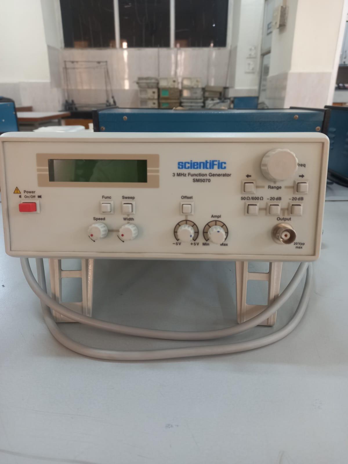
function generator 1 – sm5070
Button 1 -function- to change the waveform
Button 2– sweep- when pressed on then only you can use the speed and width dial. Used to change the frequency continuously
Width dial – sets the width around which the freq changes
Speed dial- sets the speed at which the frequency changes between the set width using the width dial.
Button 3 – offset- used to give dc component to the waveform. Always check and ensure to put on the DC button on CRO to check the DC component
The dial below is used to DC voltage from -5v to +5v .
Button 4– amplitude – to change the amplitude of the waveform.
Button 5– frequency dial – is used to change the frequency, unlike the sweep button it won’t change the frequency continuously.
Button 6 – range buttons- The left range button is used to down-change the range of frequency and the right range button is used to up change the range of frequency.
-20dB buttons are used to attenuate the amplitude by 1/10 each.
50 ohm / 600 ohm buttons are used to check the output impedance of the function generator
note-: Cro has an input impedance of 50 ohms and the function generator has an output impedance of 50 ohms for maximum power transfer.3 mhz in its name stands for that the function generator can provide frequency from 1 Hz to 3 MHz.
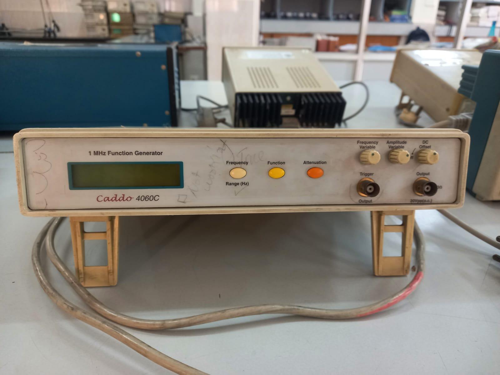
Function Generator 2 – Caddo 4060 c
Button 1 – used to change the frequency range of the function generator
Button 2– is used to change the wave form
Button 3– is used to attenuate the amplitude of the wave form.
Button 4 – frequency dial is used to change the frequency
Button 5– is used to change the amplitude of the wave form
Button 6– dc offset is used to give dc voltage
Trigger output is used as a frequency counter.