Aim :-
1. To determine the Hall voltage developed across the sample material.
2. To calculate the Hall coefficient and the carrier concentration of the sample material.
Apparatus:-
Two solenoids, Constant current supply, Four probe, Digital gauss meter, Hall effect apparatus (which consist of Constant Current Generator (CCG), digital milli voltmeter and Hall probe).
Theory :-
If a current carrying conductor placed in a perpendicular magnetic field, a potential difference will generate in the conductor which is perpendicular to both magnetic field and current. This phenomenon is called Hall Effect. In solid state physics, Hall effect is an important tool to characterize the materials especially semiconductors.
Formula :-
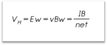
Where 𝑅𝐻 is the hall coefficient.
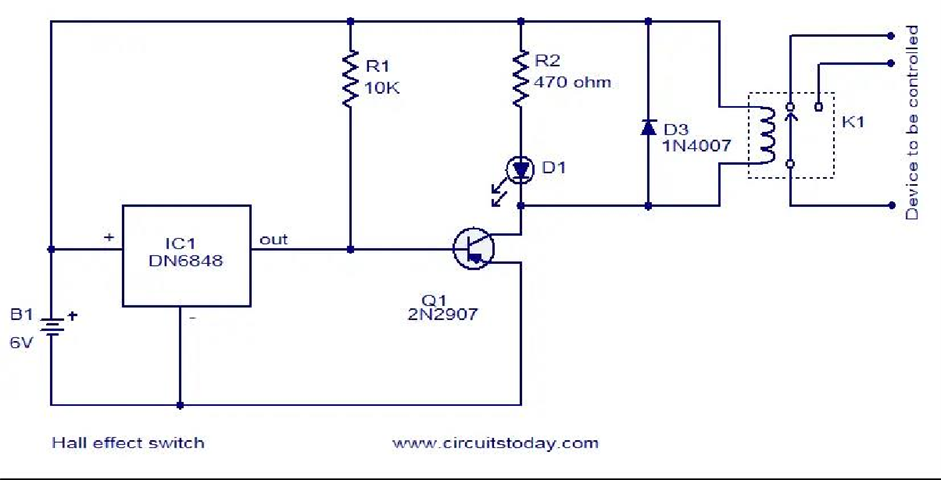
Circuit diagram :-
Observation:-
| s.no. | Magnetic field | Thickness | Hall current | Hall voltage | RH |
| 1. | |||||
| 2. | |||||
| 3. | |||||
| 4. | |||||
| 5. |
Procedure :-
- Connect ‘Constant current source’ to the solenoids.
- Four probe is connected to the Gauss meter and placed at the middle of the two solenoids.
- Switch ON the Gauss meter and Constant current source.
- Vary the current through the solenoid from 1A to 5A with the interval of 0.5A, and note the corresponding Gauss meter readings.
- Switch OFF the Gauss meter and constant current source and turn the knob of constant current source towards minimum current.
- Fix the Hall probe on a wooden stand. Connect green wires to Constant Current Generator and connect red wires to milli voltmeter in the Hall Effect apparatus
- Replace the Four probe with Hall probe and place the sample material at the middle of the two solenoids.
- Switch ON the constant current source and CCG.
- Carefully increase the current I from CCG and measure the corresponding Hall voltage VH. Repeat this step for different magnetic field B.
- Thickness t of the sample is measured using screw gauge.
- Hence calculate the Hall coefficient RH .
- Then calculate the carrier concentration n.
Precaution :-
- Hall voltage should be measured very carefully and accurately.
- The current through probe should not exceed a certain minimum value.
- The digital voltmeter should be handled carefully.
- The distance between pole pieces of the electromagnet should not be changed during the whole experiment.
Result:-
Hall coffeicent of the material = Carrier concentration of the material =