Superposition Theorem
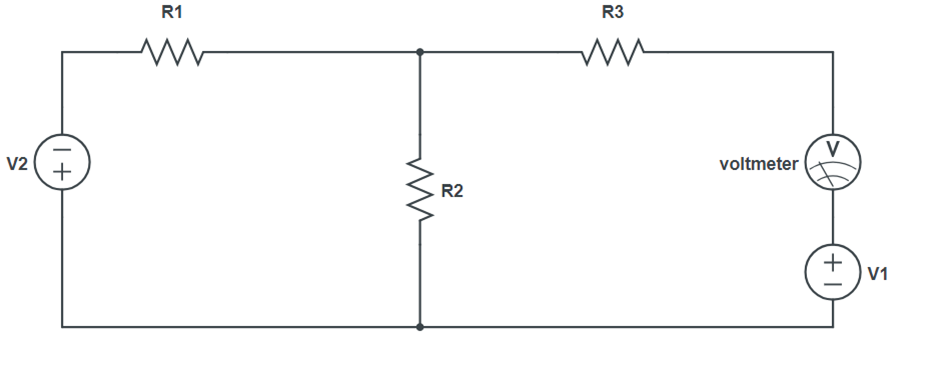
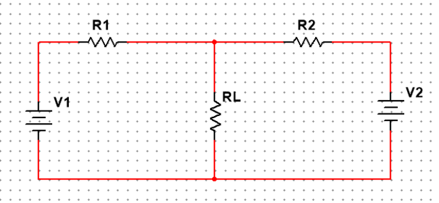
The superposition principle states that the voltage across (or current through) an element in a linear circuit is the algebraic sum of the voltages across (or currents through) that element due to each independent source acting alone.
The strategy used in the superposition theorem is to eliminate all the independent sources except one source and find the output voltage/current due to that active source using various circuit analysis techniques.
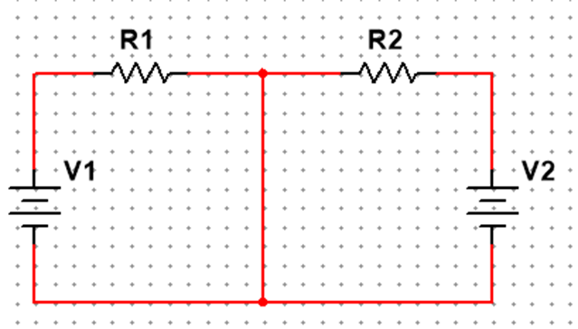
Step 1: Replace All of the Power Sources Except for One
When replacing the power supplies in the circuits, we must follow these two rules:
- Replace all voltage sources with short circuits.
- Replace all current sources with open circuits

Step 2: Calculate the Voltages and Currents Due to Each Individual Source.
We now calculate the current and voltage drop across each component due to the individual source.
Step 3: Repeat steps 1 and 2 for each power source.
Step 4: Superimpose the Individual Voltages and Currents.
When superimposing these values of voltage and current, we must be careful to consider the polarity of the voltage drop and the direction of the current flow, as the values have to be added algebraically.
Some Points to Remember
- The superposition theorem is limited to use with linear, bilateral circuits.
- The superposition theorem can be applied to DC, AC, and combined AC/DC circuits.
- The superposition theorem cannot be used to add power.
Thevenin’s Theorem
Thevenin’s theorem states that a linear two-terminal circuit can be replaced by an equivalent circuit consisting of a voltage source VTh in series with a resistor RTh, where VTh is the open circuit voltage at the terminals and RTh is the input or equivalent resistance at the terminals when the independent sources are turned off

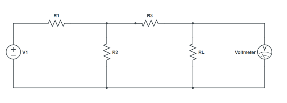
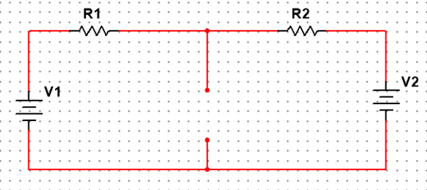
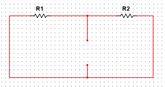
Step 1: Remove the Load Resistor to Calculate the Thevenin Voltage.
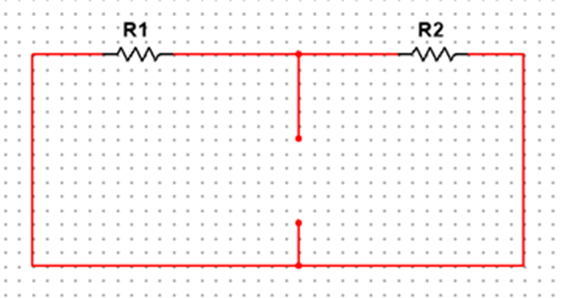
First, the chosen load resistor, RL, is removed from the original circuit replacing RL with an open circuit, as illustrated in Figure below.
Next, the voltage between the two points where the load resistor used to be attached is determined by using different circuit analysis methods.
Step 2: Replace the Power Sources to Calculate the Thevenin Resistance.
To find the Thevenin resistance for our equivalent circuit, we now must remove the power sources from our circuit in Figure above and replace them with short circuit wires, as illustrated in Figure below.
With the removal of the two power sources, the total resistance can be measured at the location of the removed load by using series or parallel combination.
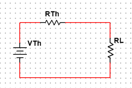
Step 3: Draw the Thevenin Equivalent Circuit.
The simplified Thevenin equivalent circuit, shown in Figure below, can now be used for calculations for any linear load device connected between the connection points.
Some Points to Remember
- This theorem can be applied to both linear and bilateral networks.
- The Thevenin equivalent circuit, if correctly derived, will behave exactly the same as the original circuit.
Norton’s Theorem
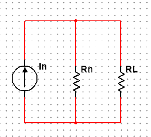
Norton’s theorem states that a linear two-terminal circuit can be replaced by an equivalent circuit consisting of a current source IN in parallel with a resistor RN, where IN is the short-circuit current through the terminals and RN is the input or equivalent resistance at the terminals when the independent sources are turned off.
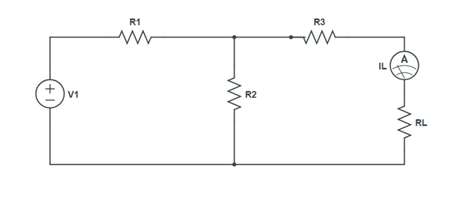
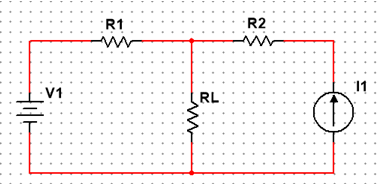
Step 1: Remove the Load Resistor to Calculate the Norton Current.
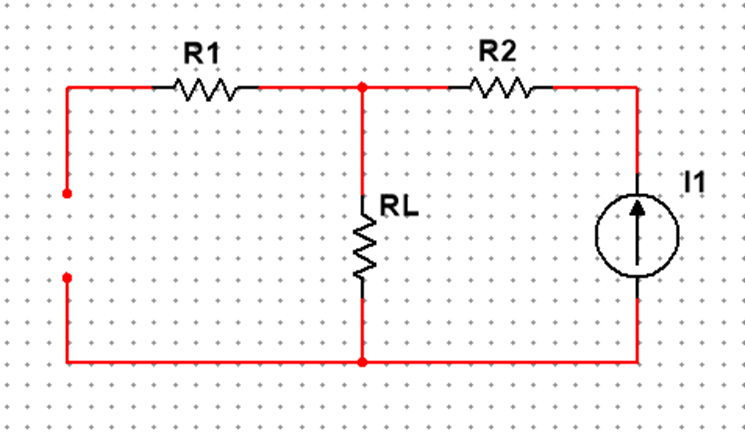
The first step is to identify the load resistance and remove it from the original circuit, as shown in Figure below.
To find the Norton current (for the current source in the Norton equivalent circuit), place a direct wire (short circuit) connection between the load points and determine the resultant current (Figure below).
Step 2: Replace the Power Sources to Calculate the Norton Resistance.
To find the Norton resistance for our equivalent circuit, we can now replace the power sources from our circuit and remove the short circuit at the load resistor point as shown in the Figure below.
After replacing the two voltage sources, the total resistance measured at the location of the removed load is calculated using series or parallel combinations of resistors.
Step 3: Draw the Thevenin Equivalent Circuit.
The simplified Norton equivalent circuit, shown in Figure below, can now be used for calculations for any linear load device connected between the connection points.
Maximum Power Transfer Theorem
The theorem states that maximum power is transferred to the load when the load resistance equals the Thevenin resistance as seen from the load (RL = RTh).
When RTh = RL
The theorem can be verified by the following steps.
- Convert the given circuit to its equivalent Thevenin circuit.
- Then replace the load resistor with the Thevenin resistance and calculate the maximum power using the above formula.
Circuit Analysis Techniques
Resistor in series: A circuit is said to be connected in series when the same amount of current flows through the resistors. In such circuits, the voltage across each resistor is different.
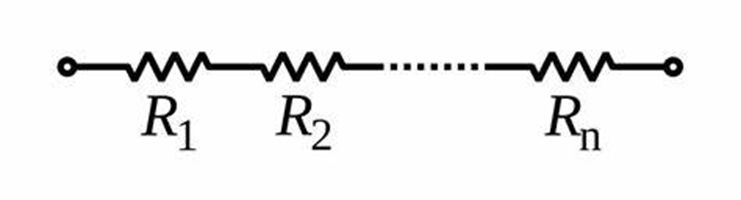
The total resistance is given as:
Rtotal = R1 + R2 + ….+ Rn
The total resistance of the system is just the total of individual resistances.
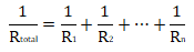
Resistors in parallel: A circuit is said to be connected in parallel when the voltage is the same across the resistors. In such circuits, the current is branched out and recombines when branches meet at a common point.

The sum of reciprocals of resistance of an individual resistor is the total reciprocal resistance of the system.
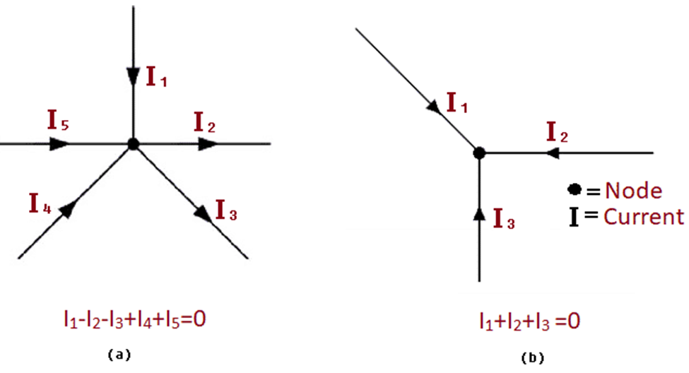
KIRCHHOFF’S CURRENT LAW (KCL):
“The algebraic sum of all the currents at any node in a circuit equals zero”.
i.e., Sum of all currents entering a node = Sum of all currents leaving anode.
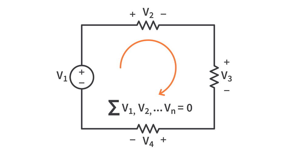
KIRCHHOFF’S VOLTAGE LAW (KVL):
“The algebraic sum of all the voltages around any closed loop in a circuit equals zero”.
i.e., Sum of voltage drops = Sum of voltage rises