AIM-
To study the VI characteristics of SCR.
APPARATUS-
NV6530 SCR Characteristics Trainer, Wires
THEORY-
SCR is a four-layered semiconductor device that is alternative of P-type and N-type semiconductor silicon. Junction J1, J2 and J3 (J1, J2 and J3 operate in forward direction while middle operates in reverse direction) and three terminals known as anode A, cathode K and gate G. The function of the gate is to trigger the device into conduction by the application of a small voltage.
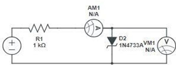
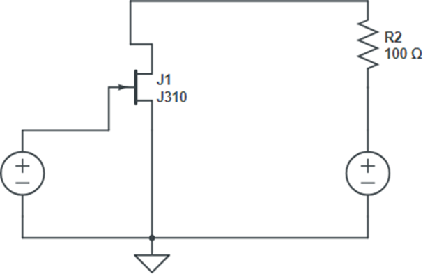
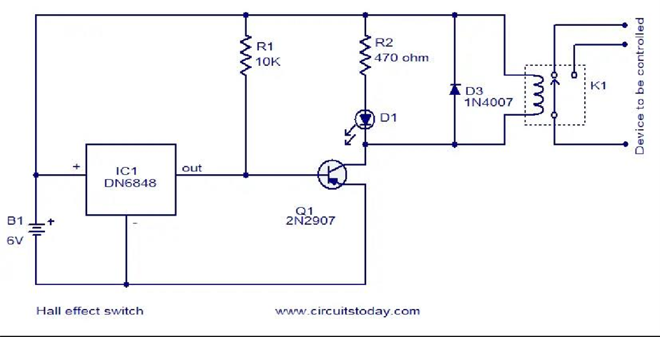
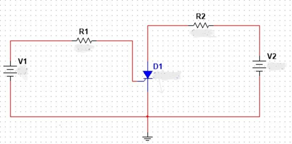
CIRCUIT DIAGRAM-
PROCEDURE-
- Connect terminal 1 to terminal 4, terminal 2 to terminal 8, and terminal 3 to terminal 12.
- Connect a voltmeter across terminals 7 and 8 and an ammeter across terminals 9 and 10.
- Make short terminals 5 and 6.
- Rotate the knob P1 and P2 fully in counter clockwise.
- Switch on the Power Supply.
- Set the value of the anode voltage at 35V by using the knob P1.
- Increase the gate current, and the voltmeter reading falls to almost zero. This action indicates the firing of SCR.
- Note the gate’s current value at this position.
- Keep the current constant by shorting terminals 9 with 10 and connecting the ammeter to terminals 5 and 6.
- Rotate the potentiometer P1 fully in counter-clockwise.
- Rotate knob P1 gradually and record the anode current for the respective value of anode voltage.
OBSERVATION TABLE-
| Anode Voltage | Anode Current [Gate Current = 7mA) |
Result-
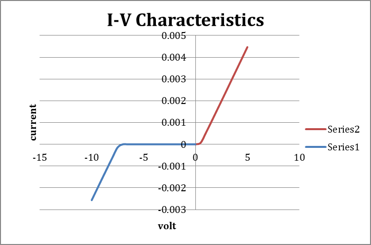
VI Characteristic graphs of SCR are obtained where the gate current is Ig=7mA. Thus,, it is observed that the current increases after V.
PRECAUTIONS-
- Avoid double connections, if possible.
- The connection should be proper and tight.