AIM-
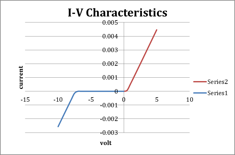
To study the VI Characteristics of TRIAC with positive and negative biasing and plot the curve between V and I.
APPARATUS-
NV6532 Charactersiitc Trainer, Patch Cord, Wires
THEORY-
A semiconductor device that is used to control the negative and positive half cycles is called “TRIAC”. The word “tri” indicates that the device has three terminals and “ac” means that the device is used to control alternate current or current in either direction.
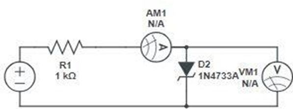
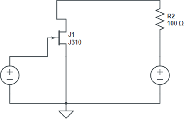
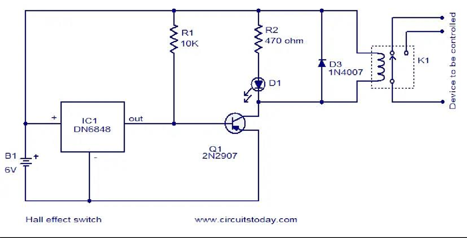
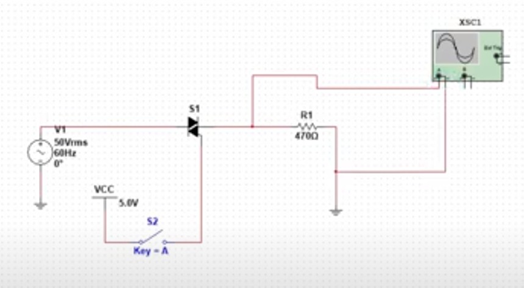
CIRCUIT DIAGRAM-
PROCEDURE-
VI Characteristic with Positive Biasing
- Make connections as shown in figure.
- Connect +35V DC Supply to the circuit by connectinf point 1 with point 5.
- Rotate potentiometer in anti-clockwise direction.
- Connect point 4 with point 9 to make common ground.
- Connect the posiitv and negative terminal of the voltmeter to point 8 and point 9.
- Conect the positive and negtaive terminal of ammenter to point 6 and point 7.
- Connect the main cord to the trainer and switch “ON” the power supply.
- Rotate P1 and increase the anode voltage slowly.
- Remove the ammter between point 6 and 7 and connect across point 11 and 10.
- Set the value of gate current near about 0.5mA.
- If the breakdown is not achieved then increase the gate current and repeat steps.
VI Charactersistic with Negative Biasing
- Now connect the -35V DC Supply to the circuit and repeat all the steps.
- Observe the gate current for which breakdown is achieved and plot the graph between V and I.
OBSERVATION TABLE-
Positive Biasing
| TRIAC Voltage (in V) | TRIAC Current (in mA) |
Negative Biasing
| TRIAC Voltage (in V) | TRIAC Current (in mA) |