Aim :
Study of the I-V characteristics of the UJT.
Apparatus:-
Unipolar junction diode, 2 Batteries, Ground element, Connecting wires, Resistances etc.
Theory :-
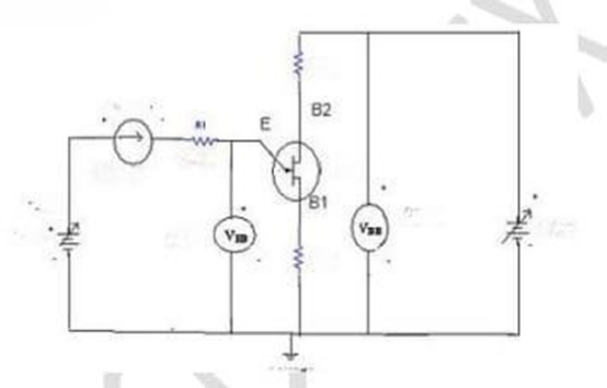
A Unijunction Transistor (UJT) is an electronic semiconductor device that has only one junction. It has three terminals an emitter (E) and two bases (𝐵1 and 𝐵2). The base is formed by lightly doped n-type bar of silicon. Two ohmic contacts 𝐵1 and 𝐵2 are attached at its ends. The emitter is of p-type and it is heavily doped. The resistance between B1 and B2, when the emitter is open circuit is called inter base resistance. The original UJT, is a simple device that is essentially a bar of N type semiconductor material into which P type material has been diffused somewhere along its length.
Circuit diagram:-
Procedure :-
- Connection is made as per circuit diagram.
- Output voltage is fixed at a constant level and by varying input voltage corresponding emitter current values are noted down.
- This procedure is repeated for different values of output voltages.
- . A graph is plotted between 𝑉𝐸 and 𝐼𝐸 for different values of VB1B2
Observation:-
| S.NO. | V𝐵1𝐵2 = | V𝐵1𝐵2 = | ||
| VE(volts) | IE(ma) | VE(volts) | IE(ma) | |
| 1 | ||||
| 2 | ||||
| 3 | ||||
| 4 | ||||
| 5 | ||||
| 6 | ||||
Precaution:-
- While doing the experiment do not exceed the rating of the UJT. This may lead to damage the UJT.
- Connect voltmeter and ammeter in correct polarities.
- Do not switch On the power supply unless you have checked the circuit connections as per the circuit diagram.
Result :- The I-V characteristic graphs of Unipolar junction transistor are obtained and are verified with their proven results.