Zener diode
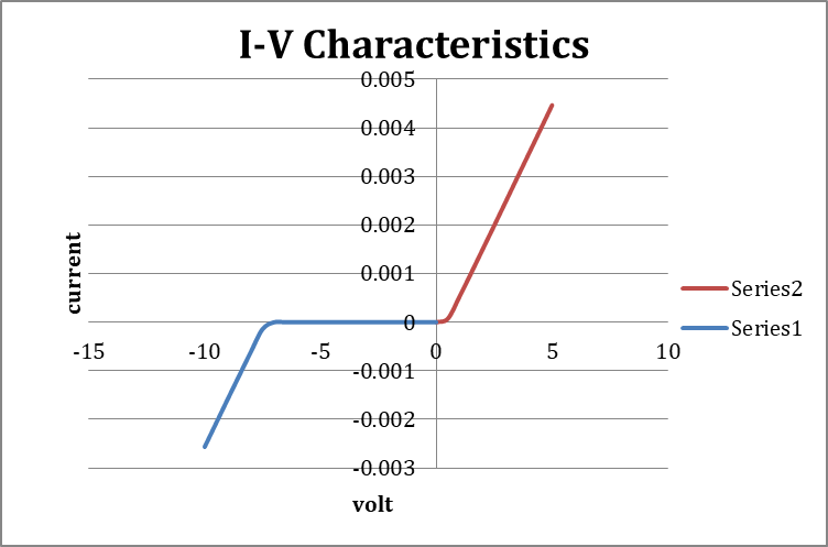
Aim:- To study the I-V Characteristics of Zener Diode.
Apparatus :- : Zener Diode, Battery, Connecting Wires, Resistances, Voltmeter, Ammeter, etc.
Theory:-
Forward biasing:- An external voltage applied with the polarity such that negative terminal of battery is connected to n –side of junction and the positive terminal of battery is connected to p- side is called a forward bias.
Reverse biasing:- The negative terminal of battery is connected to p- side of junction the positive terminal is connected to n- side is called a reverse bias. Zener diode is used in its reverse bias.
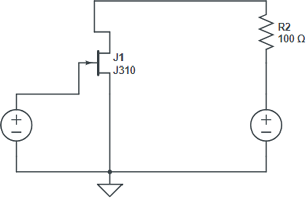
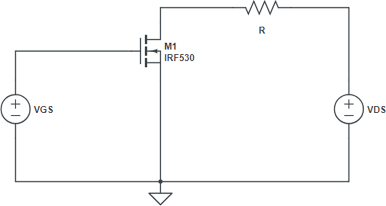
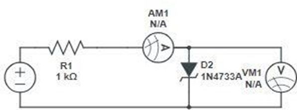
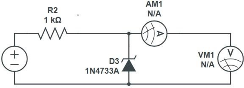
CIRCUIT DIAGRAM:-
Forward bias:-
Reverse bias:-
Procedure:-
- Connect a current wiring resistor in series with diode.
- Vary the value of input dc supply in steps.
- Note down the ammeter & voltmeter readings for each step..
- Use data and plot on I versus v graph.
Obsevations:-
Forward bias:-
| S.no. | Voltage(v) | Current(ma) |
| 1 | ||
| 2 | ||
| 3 | ||
| 4 | ||
| 5 | ||
| 6 |
Revese bias:-
| S.no. | Voltage(v) | Current(ma) |
| 1 | ||
| 2 | ||
| 3 | ||
| 4 | ||
| 5 | ||
| 6 | ||
| 7 | ||
| 8 | ||
| 9 |
Precaution:-
- Keep the circuit neat and clean .
- Check if power supply and ammeter are working properly.
Result:-The V-I Characteristic Graphs/Curves of (both in reverse and forwardbiases) as well as Zener Diode are obtained and are verified with their proven results.
Breakdown Voltage =
Max. Forward Current = 1A